Power system dynamics
Lesson 1: Load frequency control
In an electric power system (EPS), the balance of production and consumption must always be satisfied. A mismatch between these two factors causes frequency deviations. The frequency stability of EPS mostly relies on the inertia in the rotating masses of synchronous generators.
The inertial response immediately acts after a disturbance occurs and synchronous generators will release or absorb kinetic energy to the network to oppose the change of frequency and consequently the unit rotating speed will decrease or increase. The inertial response cannot be controlled because it is an inherent property of synchronous connected generators.
After the inertial response, the primary frequency regulation promptly initiates its operation. The primary frequency regulation involves the action of turbine speed regulators. The aim of primary frequency regulation is to equilibrate power generation and consumption within 15-20 seconds after a disturbance and to stabilize the frequency at a value different from the nominal. Turbine regulators adjust the working fluid flow through the turbine to modify power plant output in response to a frequency deviation.
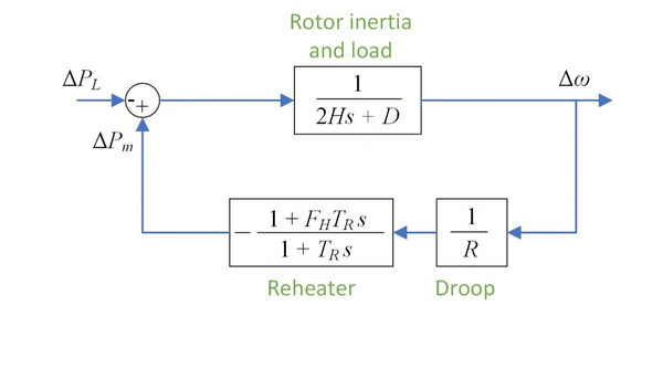
To analyse power system frequency dynamics, a block diagram representation of a single-machine power system model is developed and shown below. The dynamic model from figure is described by the equations on the right.


In this case, the low-order model of a reheat steam turbine is used. The parameters are as follows:
H – inertia constant [s]
D – load damping constant [p.u.]
R – droop [%]
s – Laplace variable
FH– fraction of the power
TR– reheat time constant [s]
PL– step load disturbance [p.u.]
Pm– mechanical power [p.u.]
Δω – rotor speed (frequency) deviation [p.u.]
Frequency regulation’s primary function is to prevent a drop in frequency below the threshold level that triggers under-frequency load shedding. The minimum allowable frequency value differs between systems, typically ranging between 49.00 Hz to 49.20 Hz.
By utilizing the interactive graph displaying the frequency response of the system provided below, it can be observed how each parameter influences the frequency response.
To achieve the satisfied frequency response, the system operator has the ability to manipulate solely two parameters: the inertia constant (increasing the number of synchronous generators in operation) and the droop constant (which entails modifying the value of an individual turbine regulator).


